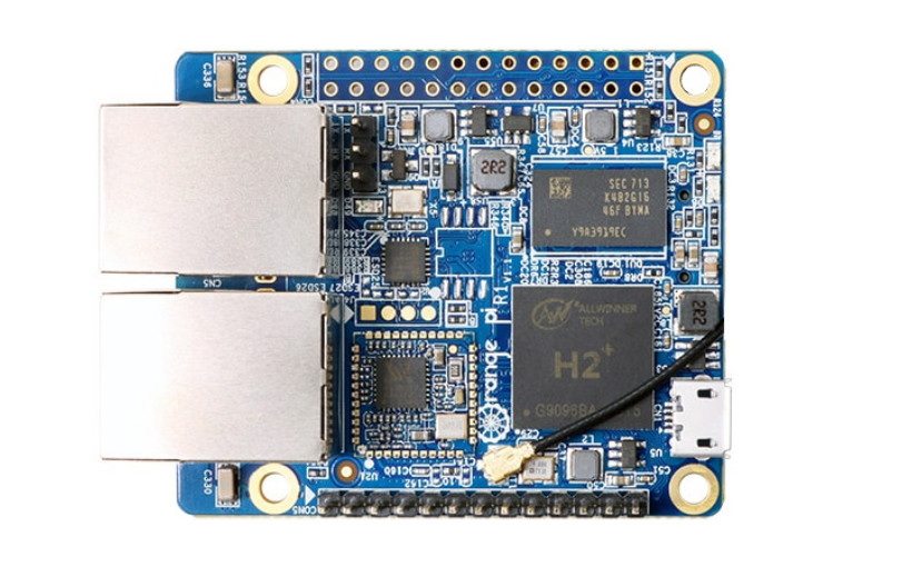
Orange Pi R1 #

Hardware Specification #
| Feature | Description |
|---|---|
| CPU | ARM Cortex-A7 Quad-Core |
| GPU | ARM Mali400 MP2 |
| Memory | 256mb DDR3 |
| Storage | MicroSD Slot,SPI Flash( 16MB) |
| Networking | Realtek RTL8189FTV, IEEE 802.11 b/g/n Onboard Ethernet 10/100Mbps 100M/10M Ethernet RJ45(RTL8152B) |
| Video Outputs | CVBS via Pinheader |
| USB | 1x USB 2.0 Host, 1x USB OTG 2.0, 2xUSB 2.0 over Pinheader |
| Debug UART | 3pins Debug UART |
| GPIO | GPIO1 26 pins |
| Power Source | MicroUSB (OTG) |
| LED | Power LED, Status LED |
| Dimension | 46*60mm |
Product’s Life Cycle #
| Parameter | Status |
|---|---|
| Production status: | In Production |
| Expected EOL: | Not available |
| Mainline Support: | Partial |
Supported Operating Systems: #
- Armbian linux, different Debian or Ubuntu flavours to pick, active develpment
- Zeroshell Routing and Bridging Firewall Solutions
- Openwrt Project is a Linux operating system targeting embedded devices
Support Matrix:
| Project | Upstream Support | Downstream Support | Not Supported |
|---|---|---|---|
| Linux Kernel | Yes | Yes | |
| U-Boot | Yes | Yes | |
| Yocto | X | ||
| Buildroot | X |
Defconfigs/Device Tree:
Linux Mainline Device Tree : sun8i-h2-plus-orangepi-r1.dts
U-Boot defconfig: orangepi_r1_defconfig
Buildroot defconfig: orangepi_r1_defconfig
GPIO #
The Orange Pi R1 has 2 Rows of GPIOs a 2x13 row and a 1x13 row.
The numbers on the board are not the numbers that you will be able to use in your program.
There is a formula that will help you to get the GPIO number when you have the pin number:
(Position of letter in alphabet - 1) * 32 + Pin number
For example, port PB12 would map to GPIO 44:
(2 - 1) * 32 + 12 = 44
Expansion headers #
1. 13 Pin Header #
| Pin | Description |
|---|---|
| 1 | 5V |
| 2 | GND |
| 3 | USB-DM2 (combined to the pin #4, 5V and GND, this makes a USB port) |
| 4 | USB-DP2 |
| 5 | USB-DM3 (combined to the pin #6, 5V and GND, this makes a USB port) |
| 6 | USB-DP3 |
| 7 | LINEOUTR (audio output Right side) |
| 8 | LINEOUTL (audio output Left side) |
| 9 | TV-OUT (The default mode is PAL, with 720x576 resolution) |
| 10 | MIC-BIAS |
| 11 | MIC1P |
| 12 | MIC1N |
| 13 | CIR-RX (Infrared input) |
2. 26 Pin Header #
| Pin | Description | Pin | Description |
|---|---|---|---|
| 1 | 3.3 V | 2 | 5V |
| 3 | PB21 TWI2-SDA / TWI0_SDA / PA12 / GPIO12 | 4 | 5V |
| 5 | PB20 TWI2-SCK / TWI0_SCK / PA11 / GPIO11 | 6 | GND |
| 7 | PI3 PWM1 / PA06 / GPIO6 | 8 | PH0 UART3_TX / UART1_TX / PG06 / GPIO198 |
| 9 | GND | 10 | PH1 UART3_RX / UART1_RX / PG07 / GPIO199 |
| 11 | PI19 UART2_RX / PA01 / GPIO1 | 12 | PH2 / SIM_CLK / PA_EINT7 / PA07 / GPIO7 |
| 13 | PI18 UART2_TX / PA00 / GPIO0 | 14 | GND |
| 15 | PI17 UART2_CTS / PA03 / GPIO3 | 16 | PH20 CAN_TX / TWI1-SDA / PA19 / GPIO19 |
| 17 | 3.3 V | 18 | PH21 CAN_RX / TWI1-SCK / PA18 / GPIO18 |
| 19 | PI12 SPI0_MOSI / PA15 / GPIO15 | 20 | GND |
| 21 | PI13 SPI0_MISO / PA16 / GPIO16 | 22 | PI16 UART2_RTS / UART2_RTS / PA02 / GPIO2 |
| 23 | PI11 SPI0_CLK / PA14 / GPIO14 | 24 | PI10 SPI0_CS0 / SPI1_CS / PA13 / GPIO13 |
| 25 | GND | 26 | PI14 SPI0_CS1 / SIM_DET/PA_EINT10 / PA10 / GPIO10 |